Building: Amp Boards on Heat Sinks
Now it's time to finish our amp boards by installing the IRFP240 N-channel power MOSFETs (Q5, Q6, Q7, Q8).
If you haven't already, now is the time to unbox the DIYAudioStore 4U Deluxe chassis kit. Unwrap one of the heat sinks, leave the rest for later. Also, you'll want to open up the DIYAudioStore Back Panel Kit now, as it includes mounting hardware that we will need. In addition, we'll need 4 additional M3 split washers that are not (but should be!) included in the back panel kit.
OK, let's go!
Step #1: Stand-offs
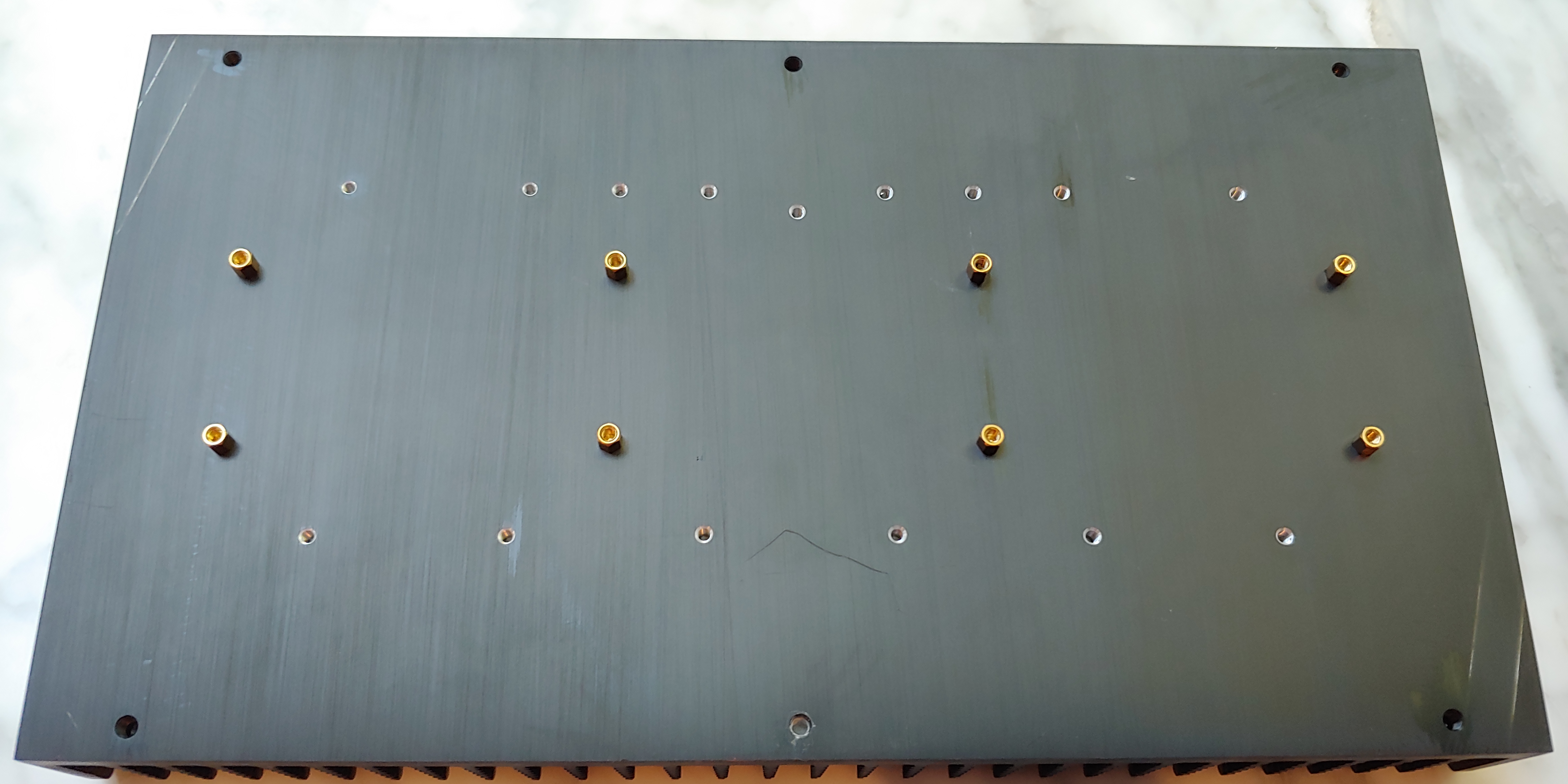
Install the eight 3mm stand-offs on the heatsink. These are the brass stand-offs that were included with the DIYAudioStore back-panel kit. Your amp board will sit atop these.
Step #2: Bend your MOSFET leads
Bend the MOSFET leads 90 degrees. You will want to bend them where they narrow.

Step #3: De-burr
Because the MOSFETs must be electrically insulated from the heat sink surface by the Keratherm pads, it's important that there are no small metal burrs on the metal face of the MOSFETs that could penetrate the Keratherm pads. In order to be sure, gently rub the MOSFET in a circular motion on 800 grit sandpaper. Wipe away any dust.

Step #4: Affix MOSFETs to Heat Sinks
The MOSFETs install on the side of the heat sink with 6 pre-drilled holes (not the one with 9 holes -- that's for different DIYAudio projects).
Before you mount them, use your 800 grit sandpaper to lightly sand around the 4 holes where you will be mounting the MOSFETs (see photo below), to ensure that any metal shavings left from tapping the holes are smoothed away (as with sanding the MOSFET contact surfaces, we want to prevent any stray bits of metal from piercing the Keratherm pads and shorting the MOSFETs to the heat sink). Wipe to remove any dust created.
FOR NOW, INSTALL ONLY FINGER TIGHT (we might need a little play to get the fit to the amp board correct).
Here's the order of parts from the face of the heat sink:
- Keratherm pad: peel this away from its backing, clear the screw hole, lay the pad on the heat sink (either side up, doesn't matter);
- MOSFET;
- Fender washer: included with the back panel kit;
- M3 split washer: these are NOT included with the back panel kit, so you will have to source these from your local hardware store;
- M3 machine screw: included with the back panel kit (use the longer ones).
A picture to make it clear:

Install four of these onto the heat sink, corresponding to the holes on the amp board (so leave the two middle holes on the heat sink empty). REMINDER, INSTALL ONLY FINGER TIGHT.

Step #5: Fit Amp Boards and Secure the MOSFETs
Carefully fit your amp board over the MOSFET leads. Gently adjust the leads and orientation of the MOSFETs until all leads fit into corresponding holes for Q5, Q6, Q7, and Q8. Secure the amp boards to the standoffs using the short M3 screws (included with back panel kit). SECURE THESE ONLY FINGER TIGHT.
Once you are confident that the MOSFET leads are correctly positioned when the amp boards are screwed onto the stand-offs, now is the time to tighten the MOSFETs to the heat sink (the L wrench included with the 4U Deluxe chassis kit also fits the M3 screws in the back panel kit, so feel free to use it). Tighten until the split washers are fully compressed. Remember, this is an area where there will be a lot of thermal cycling, and you don't want these to work loose from the heat sink.

Step #6: Check MOSFET Insulation
Remove the amp board. Using the continuity function of your multimeter, check to make sure that your MOSFETs are electrically insulated from the heat sink.
When you touch your probes to the heat sink (use one of the other drilled holes, as the anodized surface of the heat sink does not conduct well) and the fender washer, there should be a beep. This confirms that your meter is working correctly, preventing any false negatives when we move to our next step...
 |
| Beep! |
When you touch your probes to the heat sink and the MOSFET leads (check all of them), there should be NO beep (which means the Keratherm pads are doing one of their jobs, electrically insulating the MOSFETs from the heat sink).
 |
| No beep! |
Step #7: Create Amp Board Wiring Harness
If your chosen signal output wire (which will connect to the speaker binding posts) isn't already twisted together, twist them together now. You will need two 12 inch lengths (a little shorter is fine, but having a little extra provides more routing options, in case you encounter hum). This twisted pair will connect your amp board to your speaker binding post on the back panel.
Reading left to right across the top of the board (MOSFETs on the bottom), solder the following lengths and colors of wire to the open labeled holes (NOT the big unlabeled ones for the mounting screws!). We are going to cut lengths a bit longer than we need, to leave room for routing and adjusting.
- V+ = 15 inches of red 16 gauge (this will connect to the V+ Euroblock connector on the power supply board)
- Out = red end of your twisted pair output signal wire (this will go to your speaker binding post)
- GND2 = black end of your twisted pair output signal wire (this will go to your other speaker binding post)
- GND1 = 15 inches of green 16 gauge (this will connect to the GND Euroblock connector on the power supply board)
- input GND = leave empty for now, as we will solder in a Euroblock connector here
- input + = leave empty for now (see above)
- input - = leave empty for now (see above)
- V- = 15 inches of blue 16 gauge (this will connect to the V- Euroblock connector on the power supply)
Next, solder in Euroblock connectors to span the input connections (GND, +IN, -IN). Make sure the connection ports are facing outward, off the board. You will connect your input signal wires here, which run from your input connector (I recommend XLR) to the amp boards. No need to connect any wires here yet.
(NOTE: I added my input Euroblock connectors late in my build, so you won't see them on the photos after those below. Take my word for it, you want to solder them in now, before you mount the boards to the heat sinks.)


As you handle the boards from this point forward, be careful not to put too much pressure on the wire-to-board solder joints. It might also make things neater if you tie the wires together with a twist-tie to keep them out of the way.

Step #8: Photo Shoot Time!
Now is the time to take a bunch of well-lit photos of your amp boards, both top and bottom, ideally from several angles. This is both for your own future vanity scrapbook, but also (and more importantly) for any future trouble-shooting by your faithful DIYAudio.com forum experts, should things not work the first time you hook it up. With the assistance of your photos, their expert sharp eyes should be able to spot bad solder joints, incorrect parts placement, or other build errors for possible fixing.

Step #9: Install Amp Board and Check for Clearance
Now is a good time to check to be sure that nothing on the under-side of the amp board is touching the heat sink. Use a flashlight and make sure that there are no stray leads or messy solder joints that poke out too far.
Assuming all looks clear, secure the amp board to the heat sink using the shorter M3 screws included in the back panel kit. (Because there is very little clearance between the board and the MOSFETs, I added two M3 flat washers between the standoffs and the board. Probably not necessary, but couldn't hurt, and the back panel kit provides a LOT of extra M3 flat washers.)

Step #10: Solder MOSFETs
Finally! Time to solder the MOSFETs to the amp board. If you gently push the pins back against the hole, it will make soldering a little easier. Be sure to completely fill the hole with solder -- it will take more solder than most of the other board joints did.
After soldering, inspect the joints closely to make sure the joints look good. Inspect both sides of the board as best you can (you'll need a flashlight to examine the underside) to make sure no solder went where it wasn't supposed to (in my build, a whisker of solder spanned two MOSFET leads, which I fortunately saw and removed). Feel free to clean any flux residue with a little isopropyl alcohol, if you like.


Step #10: Repeat steps #1-9 for the other board
The second board should go quickly, now that you've done one already. But don't rush!
Comments
Post a Comment