Building: Power Supply Board

OK, finally time to start building! This post will provide a high level description of what the power supply does, as well as a step-by-step guide to building the power supply board (additional power supply components like the transformer and rectifiers will be connected when we assemble the chassis).
What is a power supply?
In basic terms, the power supply is responsible for converting the 120 volt alternating current (AC) coming from your wall socket into something that works with the components that make up the amplifier we're building. Those components want to see direct current (DC) at approximately 24 volts (give or take a little). There are several steps to this conversion in the Aleph J that we're building:
- Your transformer steps down the 120 volt AC from your wall to 18 volt AC (or 20 volt, depending on which transformer you got) -- here's a great video explaining how that happens;
- Next, a full wave bridge rectifier converts your 18 volt AC into a pulsating 24 volt DC (well, actually more like 22 volt DC, since the bridge isn't perfectly efficient) -- the first 13 minutes of this video explains how that works;
- Finally, your filter capacitors will smooth the pulsating DC into a steady DC signal (well, very nearly steady -- there's always a little variation, known as "ripple") -- minutes 13 to 16 of this video explain how filter capacitors work.

OK, so that's what our power supply is for: turning the 120v AC from your wall socket into smooth 24 volt (or thereabouts) DC.
Step-by-Step Build Guide for the Universal Power Supply Board
If you've been following closely and looking at your Aleph J schematic, you may have figured out that the power supply board that we're going to build is actually just the filter capacitor portion of the power supply. It will be hooked up to our transformer and our bridge rectifiers when we get to chassis assembly.
And remember, if you have questions, you can probably find the answer in either the Aleph J illustrated build guide thread or the Universal PSU illustrated build guide thread on DIYAudio.
Finally, watch the first 30 minutes of this video before you start. It shows the build process for the board (the remainder of the video shows assembly and test of the supply, but he's using two transformers, and is wired for UK voltage, so details are a bit different).
Step #1: Snap Off the Diode Rectifier Section
The DIYAudioStore Universal Power Supply boards include a section for building a full wave bridge rectifier out of discrete parts. We're not going to use that portion of the board, because we are using monolithic bridge rectifiers, which package in a nice, compact component the four diodes and associated bits that make up a full wave rectifier.
So, snap that section off and discard (or use it to practice your soldering skills with some extra resistors and wires before discarding it).

Step #2: Resistors R1-10, R20, R21
Following the general rule that you should install smaller parts before larger parts, let's start with the resistors. Remember to double check against the schematic and BOM that you have the correct resistor and measure each resistor value with your multimeter before installing.
AFTER SOLDERING RESISTORS, DON'T DISCARD THE LEADS WHEN YOU CLIP THEM. WE WILL BE USING THEM FOR JUMPERS LATER.
Start with the tiny R20 and R21 resistors. These are the LED dropping resistors, which drop the voltage down to a level comfortable for your LEDs.
Next, install R1-R8, which are resistors that, together with the filter capacitors, form your filter network for reducing DC ripple (you did watch the video, right?). Orient them so that their values can be read from above, and ideally the text all runs the same direction. Also, because these can generate some heat, it's nice if you can avoid mounting them in direct contact with the board surface; leave a few millimeters of space beneath them.
Finally, install R9 and R10, again ensuring that their values are legible from above. These are bleeder resistors, intended to gradually discharge your capacitors after you turn off your amplifier, so that potentially deadly voltages don't linger after you've switched off the power switch.

After soldering parts, I like to take a close look at my solder joints using a magnifying glass (or you can use the zoom on your phone camera), just to make sure that I've got a good joint, filling the hole and most of the copper pad.

Step #3: LEDs
LEDs have a polarity, with the longer lead being the positive (or anode) side, and the short lead being the negative (or cathode) side. The longer lead goes on the more positive side of the circuit. Looking at the board from above, that means the long lead on the LED should be in the LEFT hole for both LED 2 and LED3. Also, convention seems to be red LED for V+ and green for V-, which means red LED is in the LED2 position, and green LED in the LED3 position.

Step #4: Board Connectors and Jumpers
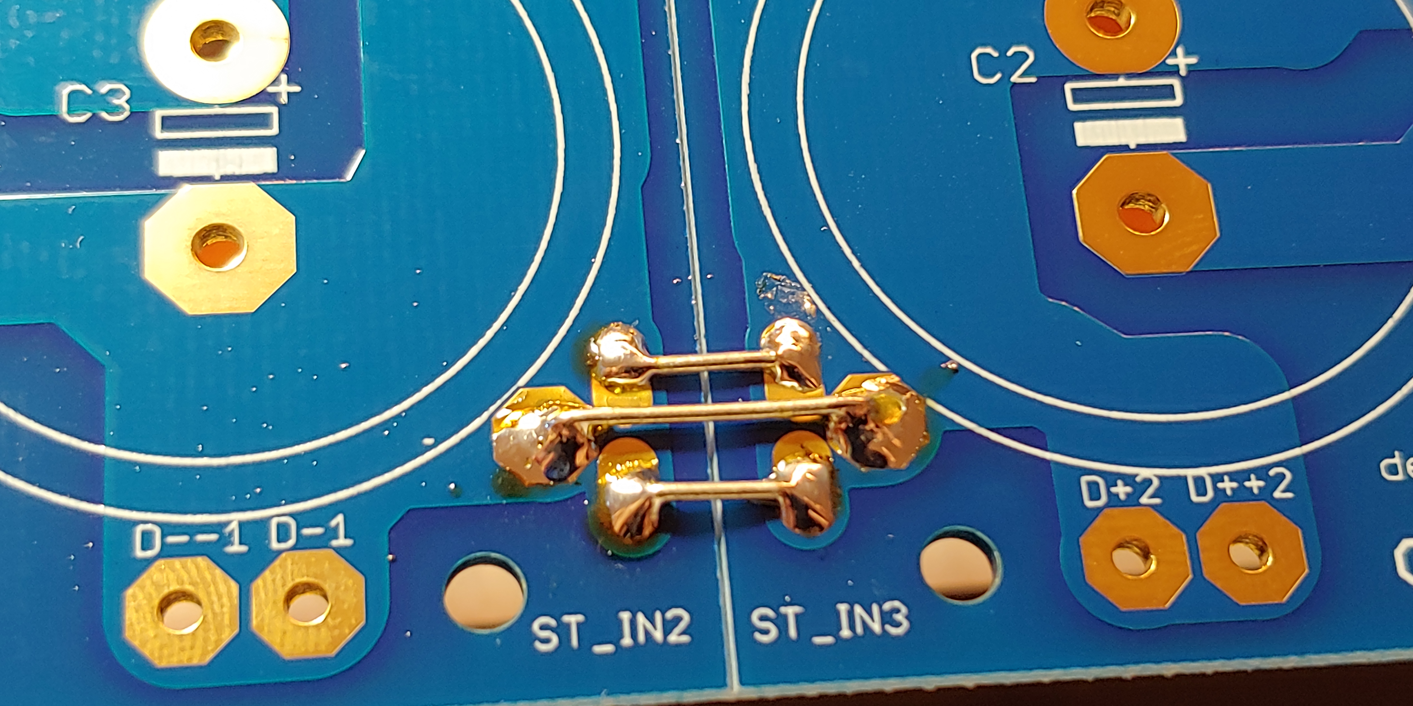
Next, we need to connect the two sides of our board to have a common ground (the PSU board is meant to be configurable in lots of ways, but for this Aleph J build, we tie the grounds together). To ensure a solid connection, solder jumpers in four spots. You can use the trimmed leads from your resistors as jumpers.

Next, we add the connectors. On the input side (the side that will connect to the bridge rectifiers), we will use the Faston blade connectors. Because these seemed like they might be a bit wobbly, I soldered on both the top and bottom sides for a firm connection. On the output side (the side that will connect to our amp boards), we will use the three-screw Euroblock terminals. Make sure you have them installed in the correct spot at the edge of the board, with the connection ports facing outward. In the end, it should like this:


Step #5: Filter Capacitors
Finally, the big capacitors! These have short "snap-in" leads that should pop snuggly into the holes on the board. Make sure they are snug and your caps flush against the board. Also, because these have a polarity, make sure you have the negative lead in the negative hole. This is made easy for you by the board labels: just make sure the big white stripe on the capacitor is oriented with the white label on the board. The white stripes should all be facing away from the resistors. If you're at all uncertain, you can double check with the photos below.
Then solder into place. Don't skimp on solder -- fill the hole and most of the copper pad. You don't want a poor connection for these big capacitors.


Step #6: Cleaning
As a final step, I used some cotton swabs and isopropyl alcohol to clean the flux residue (the clear yellowish residue left behind after you solder) from the solder joints. This isn't strictly necessary, but this remaining residue is mildly corrosive over time, as well as sticky enough to attract dust. Plus, cleaning it off just looks nicer. :-)
How does 18-20vac secondary taps get you to 24vdc in the end. How does one choose a transformer if some other output is required. Thanks. Great blog.
ReplyDeleteAC transformer voltage specs use RMS (root mean squared) average, not peak value. To get peak AC voltage, multiply by 1.414 (so 20vAC RMS = 28v peak). When converting to DC, you lose a little because the bridge rectifiers we are using are not perfectly efficient. So you end up with about ~25v DC at the end because DC voltages are (roughly speaking, after our filter capacitors reduce ripple) steady state, so they are not measured as RMS values.
DeleteThis is a cool project that made me bought a new fluke 117 electricians true rms multimeter
ReplyDeleteWith reference to the above question, if there is ~25 V DC coming away from the rectifier, what sort of amperage would be there?
ReplyDeleteI'm afraid I don't know the answer to your question. I have seen the Aleph J design described as "current limited," and you can see that power falls into 4 ohm loads (rather than doubling). Beyond those observations, I'd suggest you ask your question on the DIYAudio Aleph J forum.
Delete